Using Your Uniview NVR,UNV NVR includes Easy, Prime and Pro series, which can be adapted to different application scenarios. UNV NVR has high quality genes to ensure the reliability of devices and the whole system, focusing on user experience to simplify every operation process.
How to Add an H-series Camera to a Uniview NVR Internal Switch
In this guide, we will show how to add an H-series IP camera to a Uniview NVR.
Step 1. Configuring The H-series Camera
The best way to do this is to connect the camera directly into your computer or router and power the camera separately using a 12vDC power supply, or use a PoE switch like we used in this guide.
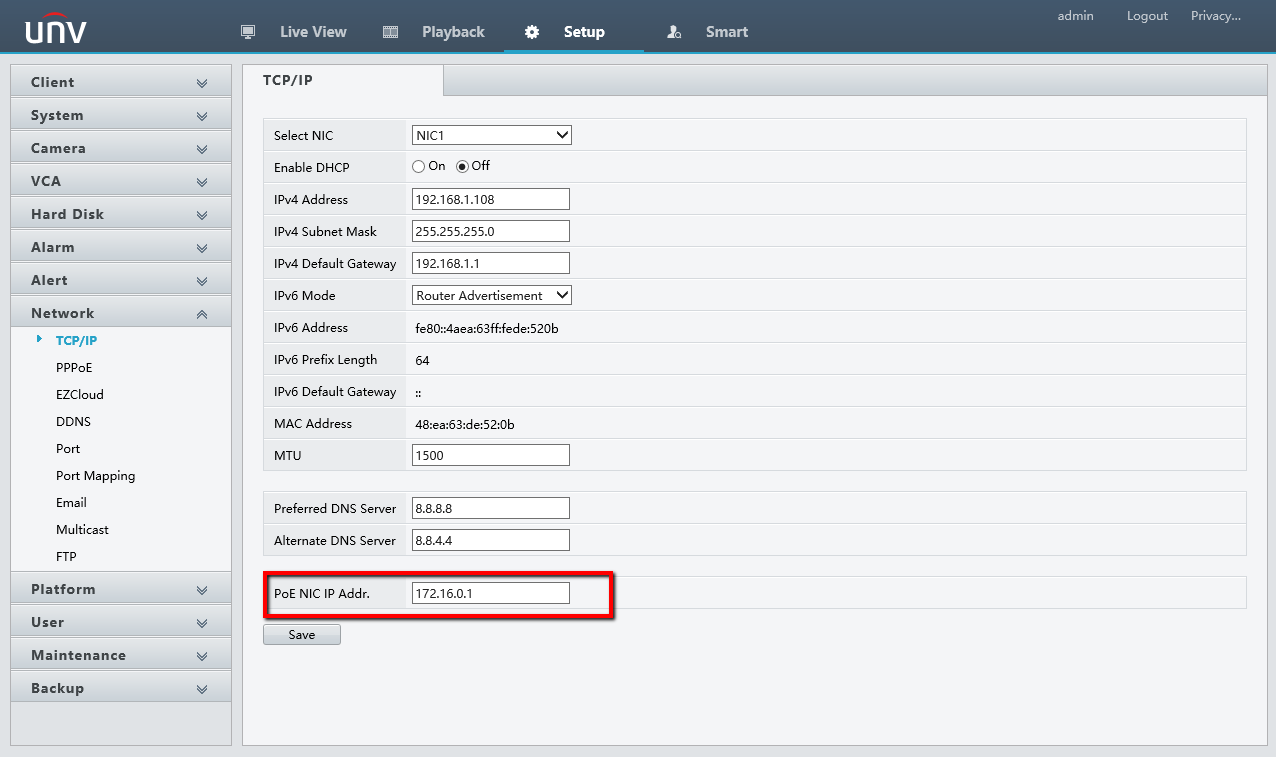
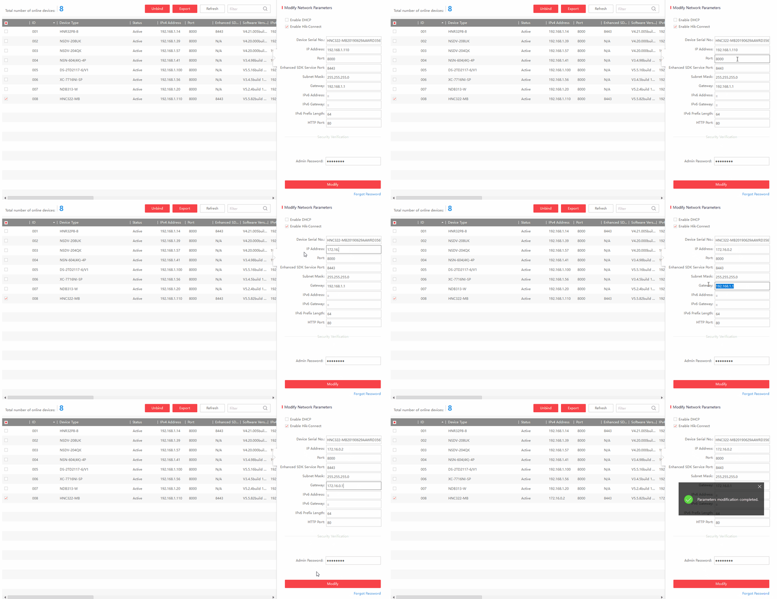
Once the camera is connected,run the SADP Tool and modify the camera’s IP address to match the internal subnet of the Uniview NVR (172.16.0.x)
In this guide, we are making the H-series camera’s IP address “172.16.0.2” and setting the Gateway to “172.16.0.1”.
Please Note!
Do not set the camera’s IP the same as the NVR’s internal IP, which is “172.16.0.1”
Using Your Uniview NVR
Read More :
- UNIARCH NVR DVR Full installation user manual
- Advanced Uniview IP Camera Guide
- How to Setup Your Uniview Security System
Step 2. Plug the H-series Camera Into the Uniview NVR and Configure
In this guide, we will be connecting the H-series camera into channel 1 on the Uniview NVR.
We are accessing the Uniview NVR via it’s web interface on Internet Explorer.
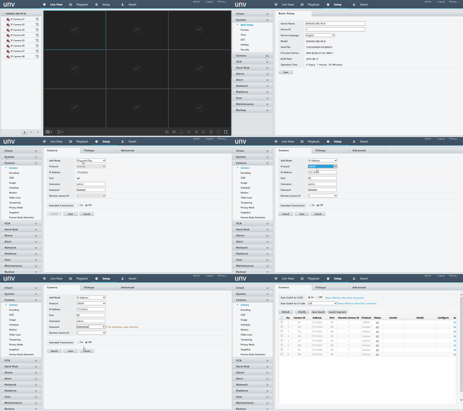
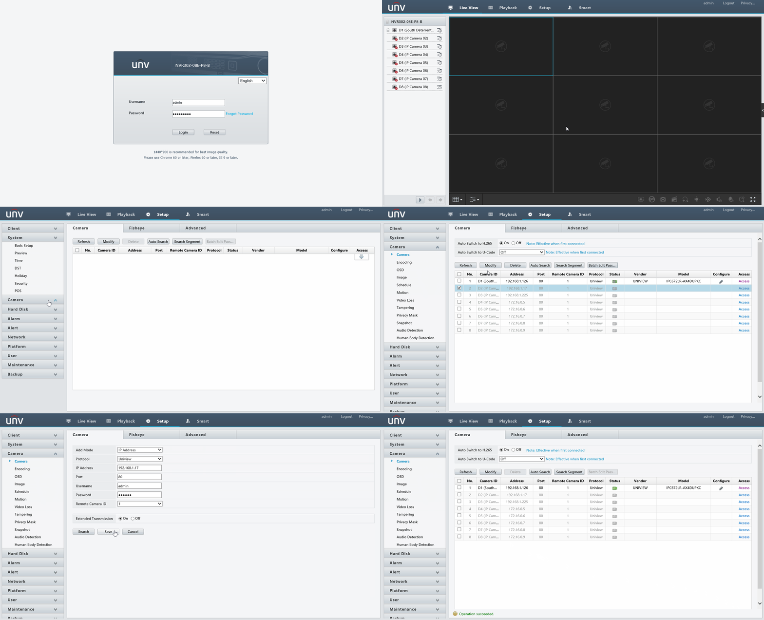
From the Live View page, Click on Setup -> Camera -> Camera
Then click on the needed channel and Modify
Change Add Mode from “Plug-and-Play” to “IP Address”
Protocol from Uniview to ONVIF
Type in the needed IP Address.
Port is 80
Then the login info for the camera.
Click Save
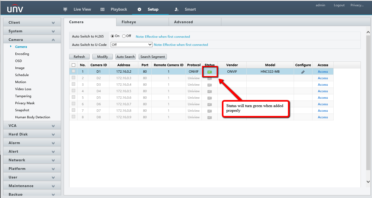
After Refreshing, the channel status will turn Green
Now it’s live! Click on the Live View Tab to see the camera
Modify OSD Settings Via Web Interface
By Default, a camera’s name when added to a Uniview NVR is it’s model number.
Having the ability to change the camera name can keep your system organized and easier to navigate.
Step 1. Log Into the NVR Via Web Interface
Log into your NVR via Internet Explorer and click on the Setup Tab at the top. Then go into the Camera on the left and lastly OSD.
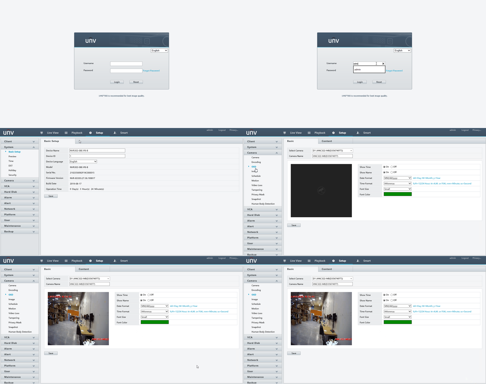
You will have to adjust and name each camera one at a time. Select the camera you want to work on from the drop-down list at the top.
Step 2. Modify OSD Settings For The Camera
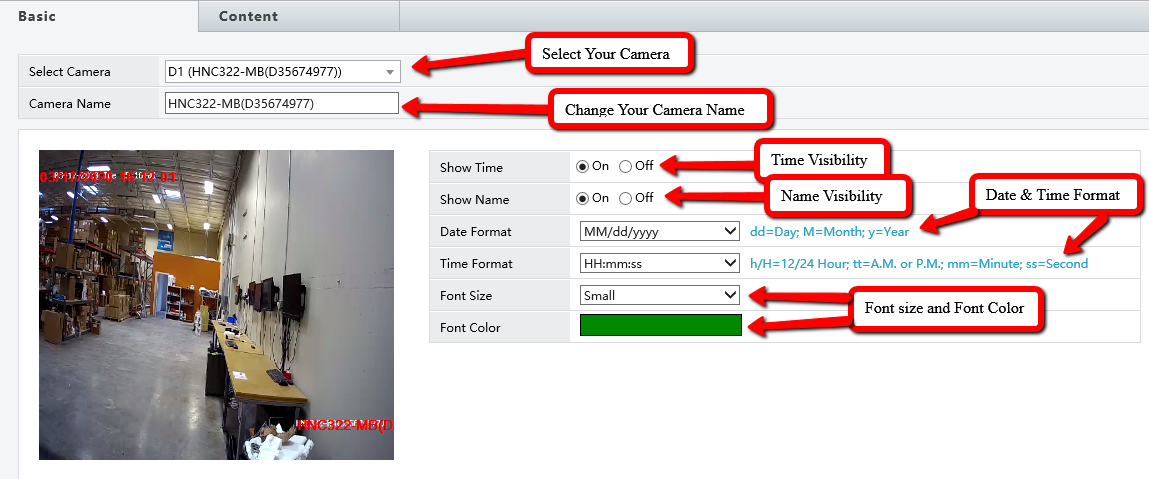
In the Basic Tab, you can modify the camera name, Name & Time Visibility, date & time Format, and Font Size & Color.
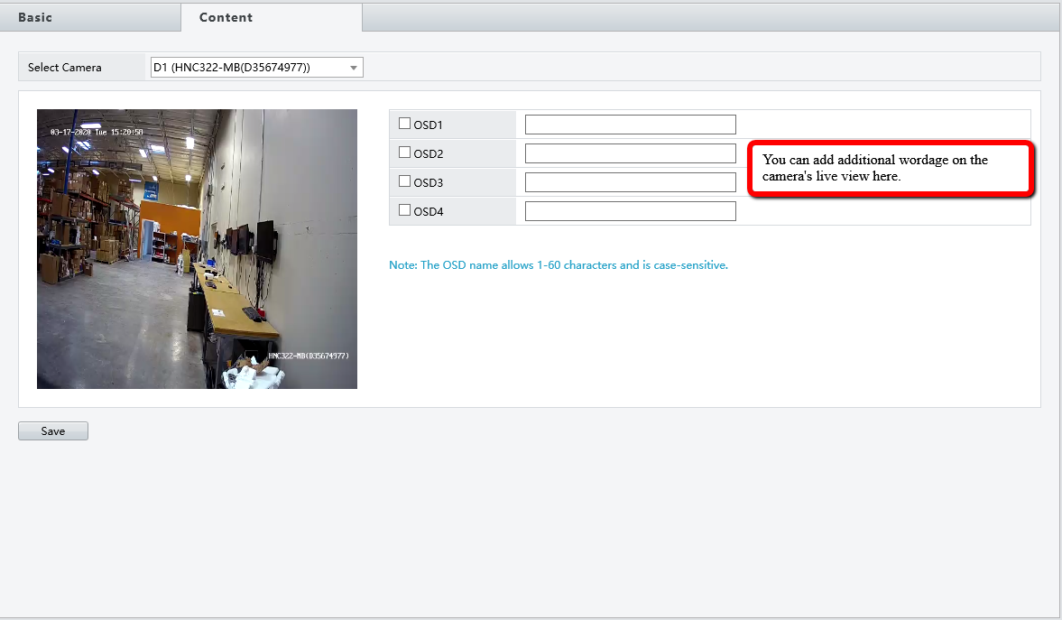
In the Content Tab, you can add additional wordage on the camera’s Live View
Setting up Uniview DDNS with EZDDNS
List of needed materials:
- Computer
- Uniview Recorder
Below you can see the web interface for a Uniview NVR. You will need to navigate to the IP address of the unit. Then go to Setup>Network>DDNS.
If you are having trouble finding your Uniview recorder then you can download the EZ Tools software to find it on your network here
Once you are in the DDNS portion of the recorder. Just turn it on and fill in the required information as shown below. Select EZDDNS you will have to create your own unique domain name.
Then click save then under device address you will see where it says en.ezcloud.uniview.com/yourdomainname. You will then use this address to access your recorder from the internet through your favorite web browser.
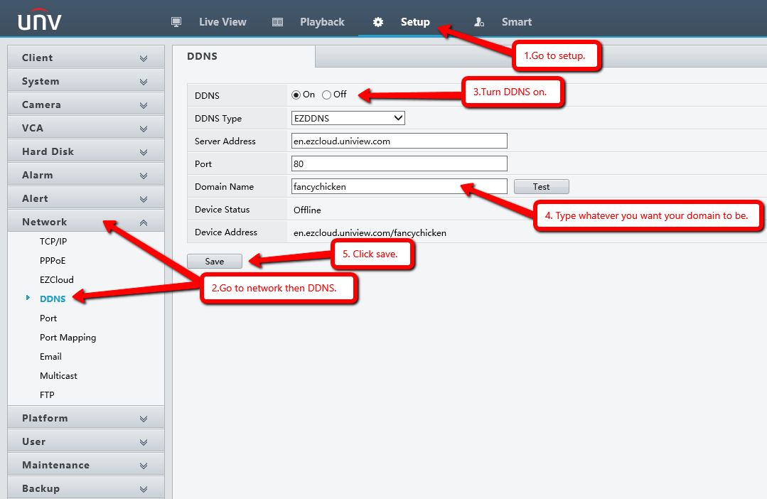
If you are setting it up from the attached monitor you can navigate to it the same way as shown below and just fill in all the information the same way.
No Video Output
The main reason a monitor would not work on a recorder is the output resolution of the recorder is too high or too low for the monitor to display. Example: The recorder could be set to 1920 x 1080 (1080P) but the monitor may only support 1024 x 720 (720P).
In this case the recorder display resolution will need to be lowered. This can be done a couple different
ways.
Method 1.
Log into the recorder via the network using an Internet Explorer browser. Navigate to the setup and then to the display settings. Adjust the resolution for the output that you are using (VGA or HDMI)
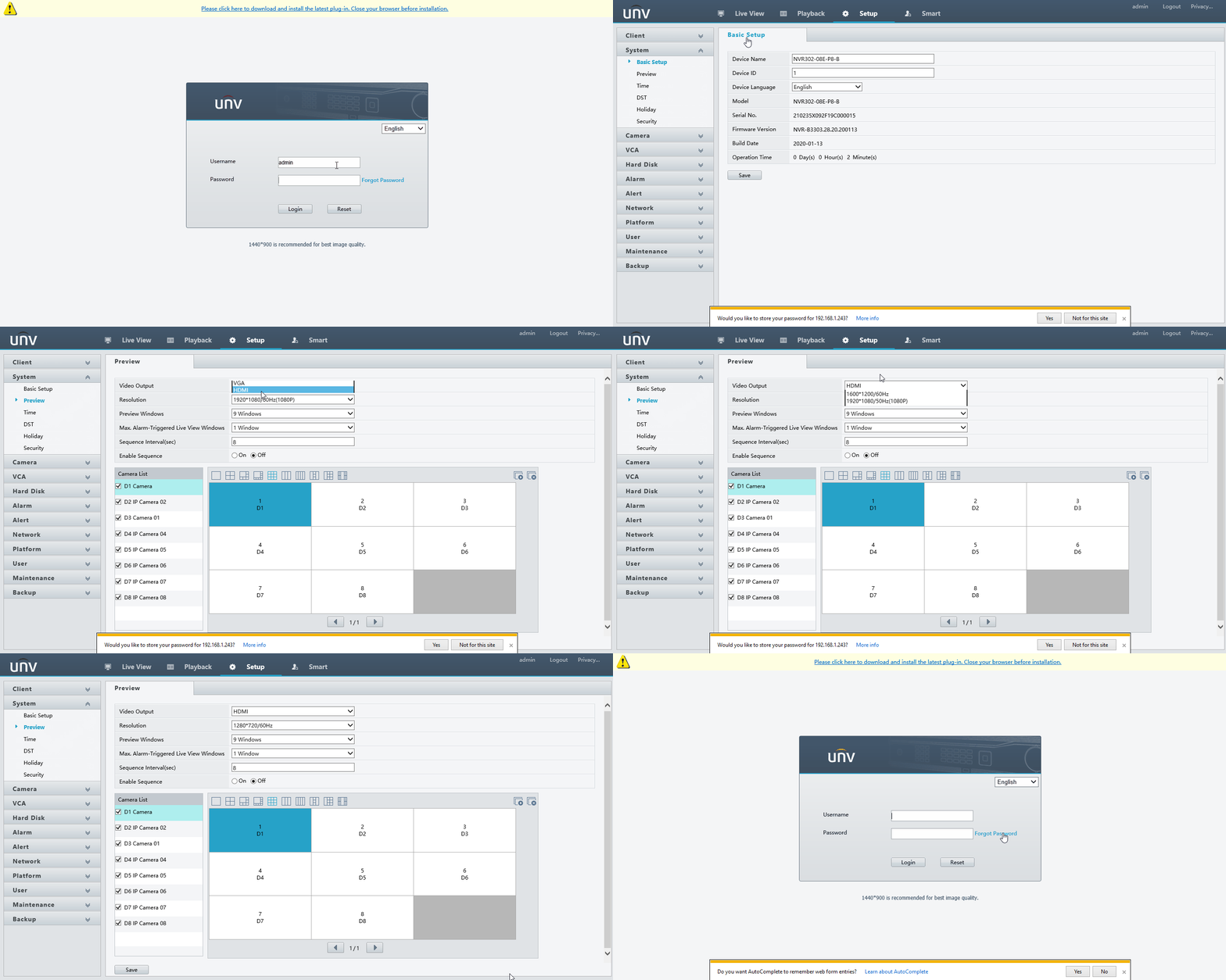
After Clicking Save, the Recorder will reboot and will output the new resolution!
Method 2.
Attach a mouse to the recorder in any of the USB ports. Press and hold down mouse 3 (Scroll
wheel) for 20 seconds then let go. The resolution of the recorder will reset to 1280 x 1024 and should
work on most monitors.
Method 3.
Double check the HDMI cables and VGA cables and make sure everything is connected on both
sides and that the monitor is on the correct source channel. Try a different monitor if this does not
work.
Password Reset
The Default Uniview admin Password is “123456”. However, this can be changed upon setup or even accidentally!
If the default password doesn’t work then you will have a few methods of troubleshooting this issue in
order to get back into your system. Your first step should be to contact your installer. Most installers
have a standard password that they assign to units they install and may be able to help resolve this for
you simply. If they do not have it then you can move on to other solutions.
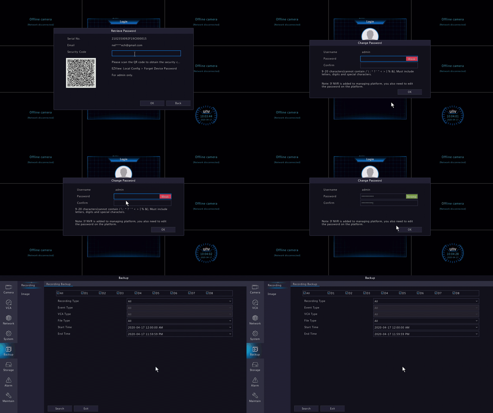
Method 1. Via EZView App
- Open the EZView application
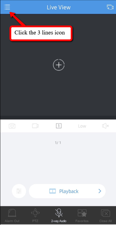
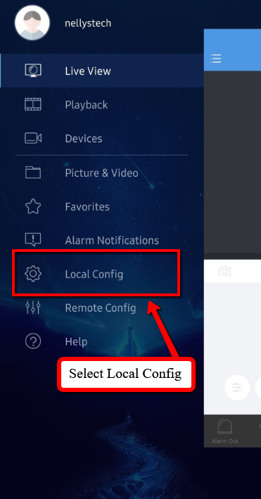
- Click the three lines in the top-left of the screen, this will bring out a pop-out menu. Select Local Config which should be the second option from the bottom.
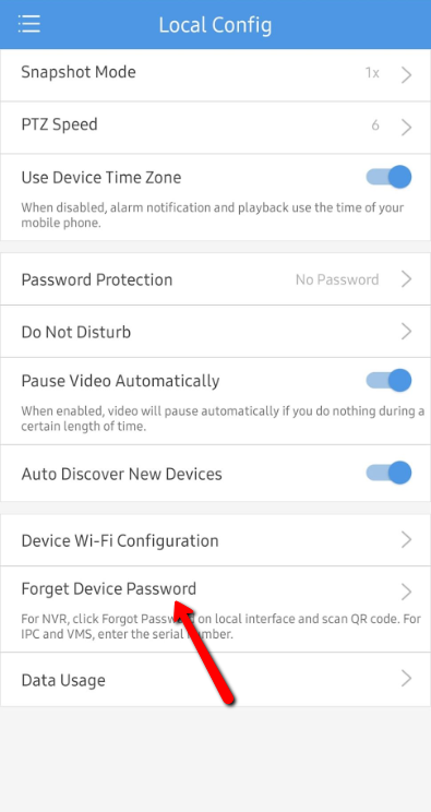
- In the configuration screen, select the Forget Device Password which is also the second option from the bottom.
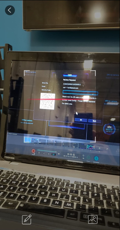
- This will open the camera of your phone if you have allowed the application to do so.
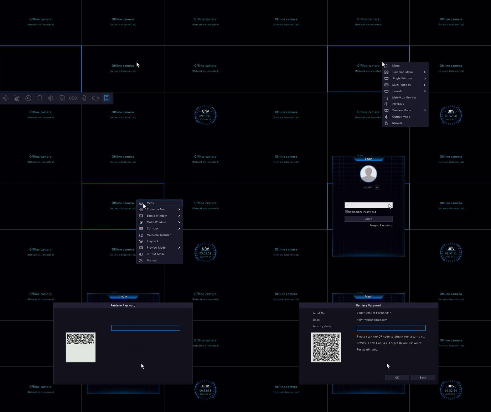
- On the unit, go to the login screen. In the bottom-right corner is the Forgot password button. Click this.
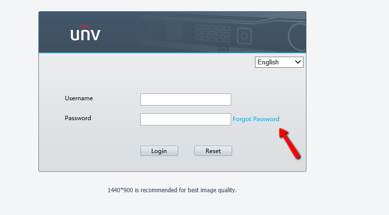
- Or From the Web Interface, select Forgot Password on the login Page
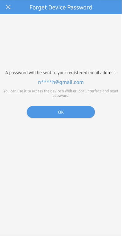
- Now using your phone scan the QR code that has been generated on the screen. This will produce a temporary password for you to use on the unit. it will be emailed to the account you set upon initial setup.
- The Web Interface will produce the same QR Code
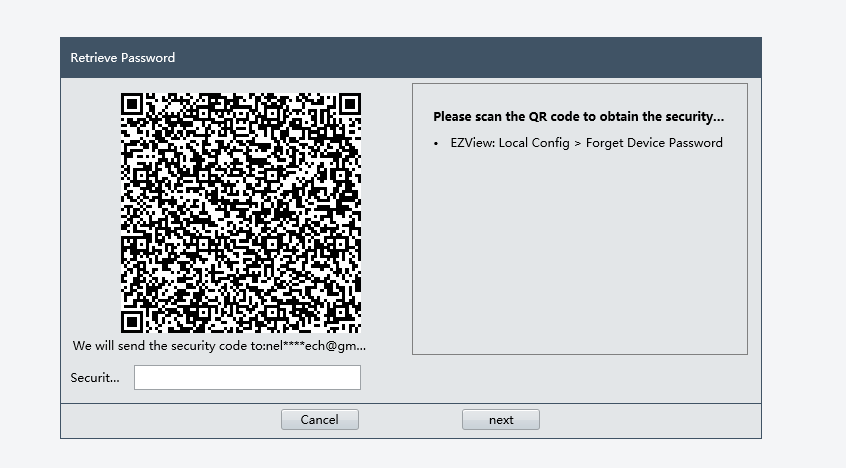
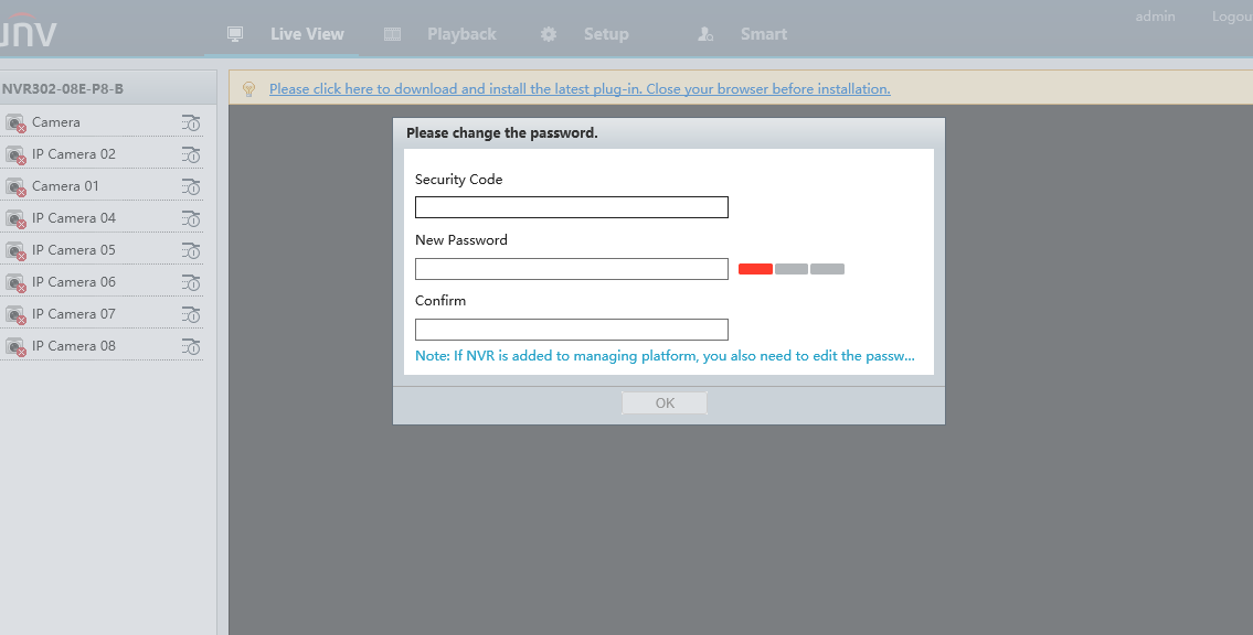
- Type in the temporary password that the is sent via email and type it into the field. After clicking okay, you will be prompted to change the password.

- The Web Interface will prompt to change the password as well before signing in
Method 2. Via EZCloud Service
The EZCloud service is Uniview’s P2P service which allows users to remotely view their units no matter
where you are (assuming you have a connection to the internet!). There are a few ways to add your unit
to the cloud service which is covered in other tutorials available on our website. This tutorial will assume
you have already added the device to your cloud account.
- Go to en.ezcloud.uniview.com
- Log into your cloud account using your credentials.
- Your devices should be listed on the screen under My Cloud Devices
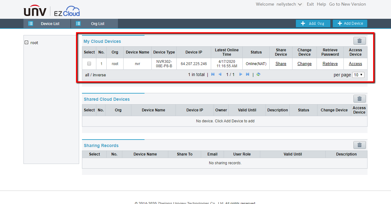
- Click the Retrieve password option on the same line as your recorder.

- You will land on a screen which requires a verification code. To have the code sent to the e-mail associated with your account click the acquire button next to your e-mail.
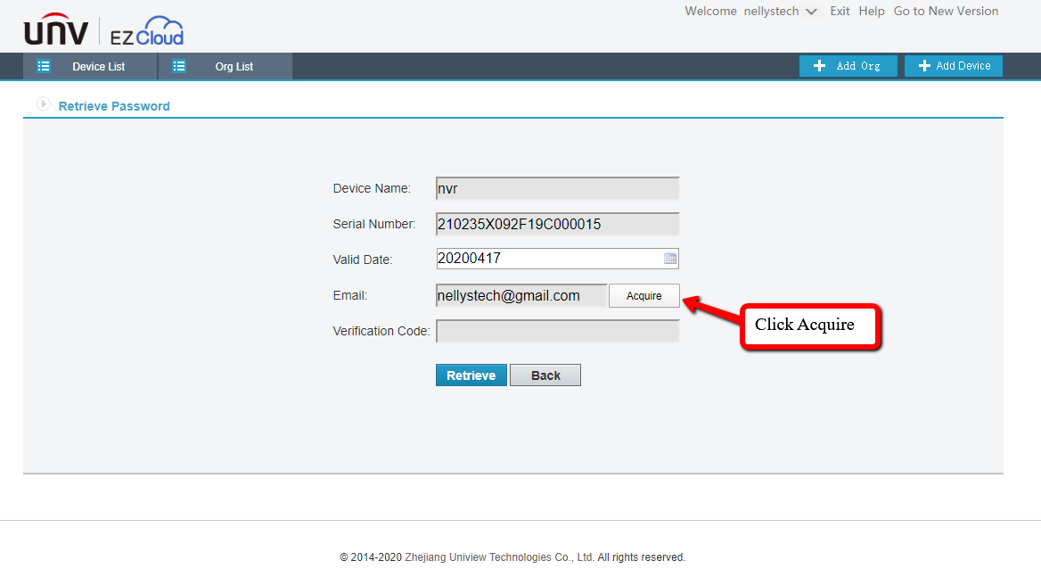
- Open your e-mail. Within a minute or two the verification code will arrive. Retrieve the verification code and type it into the EZCloud window where the verification code is requested. Note: The verification code is only valid for 30 minutes after clicking the acquire button.
- After putting in the verification code, the website will generate a temporary password just for today’s date. Type this on your unit and log in.
Accessing Cameras On PoE
Accessing Cameras On The Built-In PoE
Sometimes it is necessary to access a camera directly in a computer web browser in order to modify a setting, update firmware, or troubleshoot a problem. With most manufacturers, when using a built in PoE switch this can become a very big hassle and waste a lot of time. It would normally involve hooking a PC directly into the PoE switch and networking the computer by hand to match the built in PoE gateway. With Uniview all that hassle and trouble are in the past. Uniview NVRs allow for direct access to the camera from within the NVR, by using the NVR as a host to access the camera’s web page with the click of a button.
Accessing the Cameras
- Open the recorder’s webpage in Internet Explorer by navigating to the local IP address of the recorder.
- Login to the recorder, the default login is Username: admin and Password: 123456
- After logging into the recorder, close the change password popup if it appears and then navigate to the setup/setting menu
- Once in the settings, navigate to the Camera menu on the left hand side of the screen.
- Then navigate to the IP Camera sub menu inside the Camera menu
- A list of all the camera that are connected to the recorder will be displayed
- Locate the camera that you need access to in the list and look all the way to the right hand side of its listing
- Click on the Access button that is listed for that camera.
Next the camera will open in a new tab. This will work for cameras that are on the local network or cameras that are on a built in PoE.
Once the camera login loads, login to the camera with the default login of Username: admin and Password: admin
At this point after logging in the camera should be fully accessible and any changes, firmware updates, information, or troubleshooting that needs to be configured can be. Since you are logging into the camera directly, even though it is through the recorder, the computer has a direct network link to the camera allowing for greater access to settings than just on the recorder. This also allows for more stable and reliable firmware updates, with a better success rate. When updating the firmware of the camera this way, the computer is uploading the firmware file to the camera directly without using the NVR as a middle point.
Web Browser Access using a PC
Follow the steps below to access your Uniview device in a web browser.
Note: Cameras connected to the built in POE ports on an NVR will not show on this tool.
1. Connect the device to your router.
2. Download, install, and run the EZTools software.
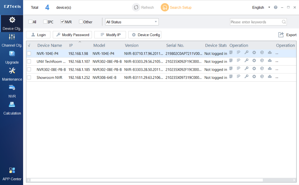
EZTools will find Uniview and ONVIF devices currently connected to your network
3. Locate the device on the list.
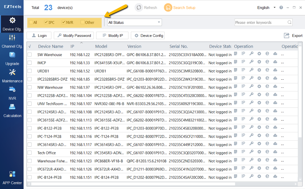
Note: You can filter which devices are shown by checking/unchecking the All, IPC, NVR, and Other boxes above the device list.
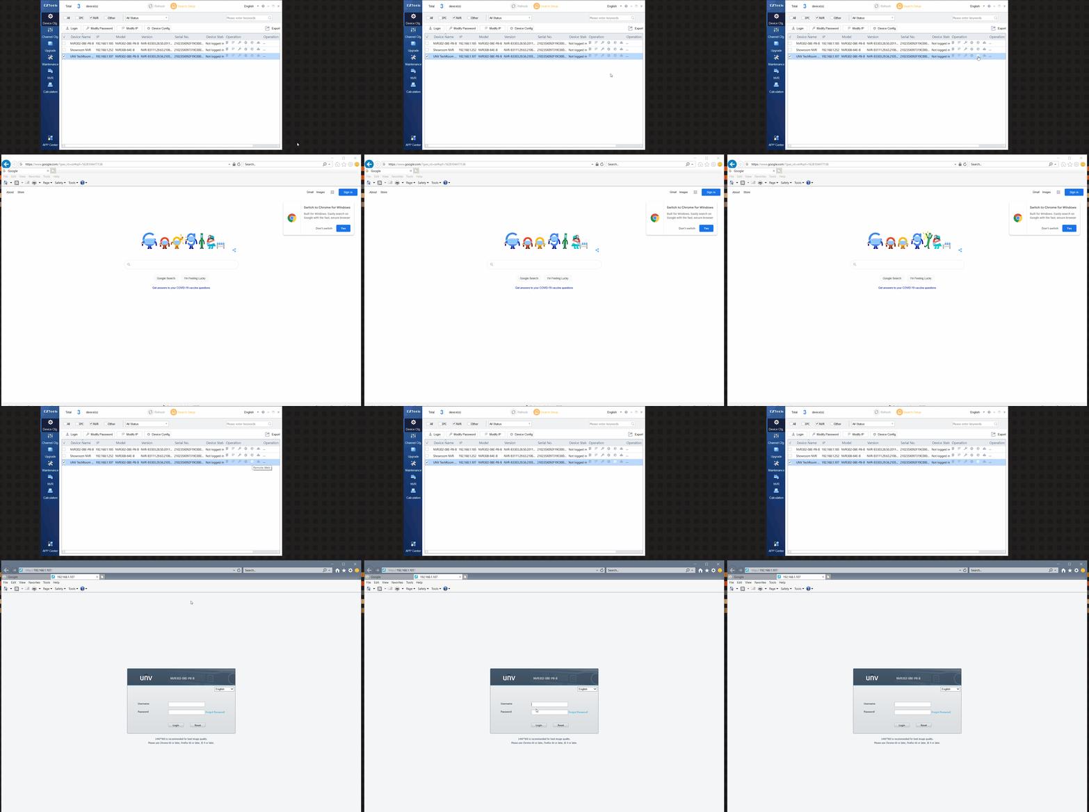
4. Click the “e” icon on the right side of EZTools to automatically open the device in your default browser.
Note: If your default browser isn’t loading a Live View use Microsoft Edge with IE Mode enabled to access the NVR.
![]()
Watch it in action
How To Monitor And Manage Your Storage
To monitor and manage your storage, you will need to access the Hard Disk group on the setup. The settings and their functions are explained below.
Hard Disk
This tab shows you details of the current storage situation of your NVR. The total capacity and the available free space can be monitored from this tab alongside options to add and more storage.
Navigation: Setup > Hard Disk > Hard Disk
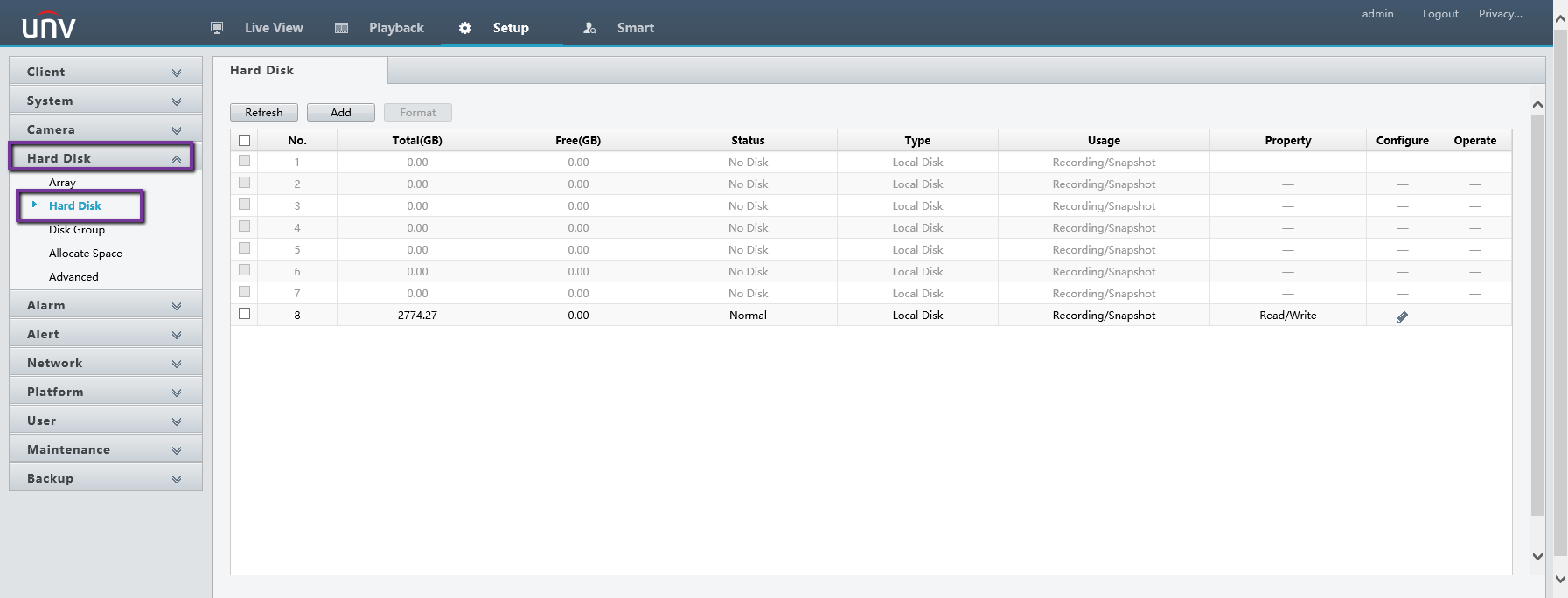
- Refresh: Activating this option refreshes the list.
- Add: Allows for the addition of a connected hard disk.
- Format: Erases the data of a hard disk by formatting partitions.
- Configure: Allows you to determine the read/write properties of each drive.
Disk Group
This tab allows the creation and management of Disk Groups. A handy tool if managing a large number of Hard Disks and to simplify storage allocation.
Navigation: Setup > Hard Disk > Disk Group
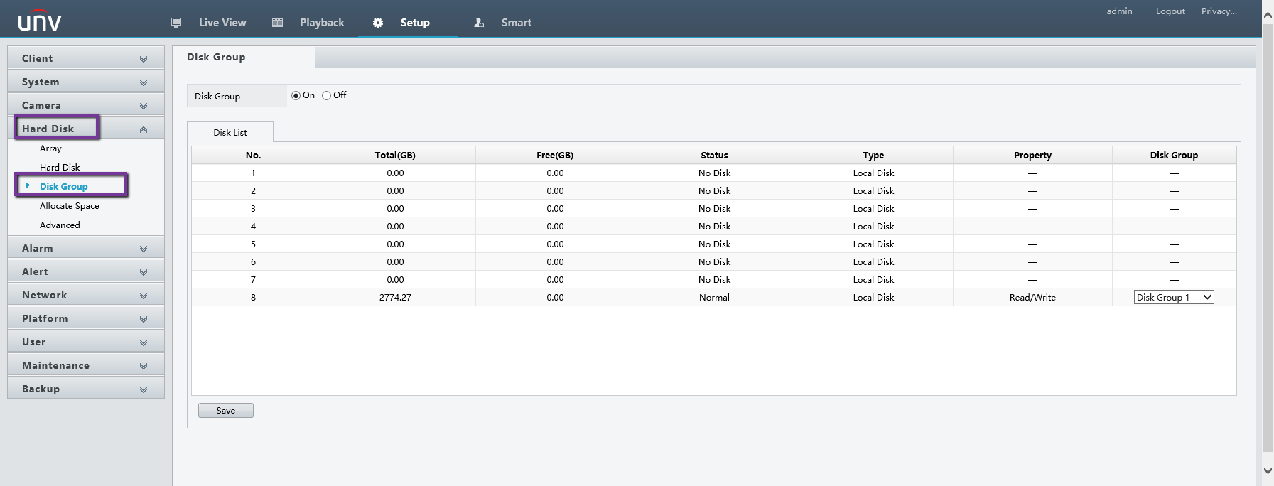
- Disk Group: Allows the creation of disk groups.
The disk group feature allows us to assign hard disks to a disk group and use the disk group to store recordings and snapshots of specified cameras. Different arrays can be assigned to different disk groups. Redundant disks cannot be assigned to any disk group. Disk group information will be initialized if any disk in the group is formatted.
Allocate Space
This tab allows setting a maximum storage allocation for each camera on a disk group.
Navigation: Setup > Hard Disk > Allocate Space
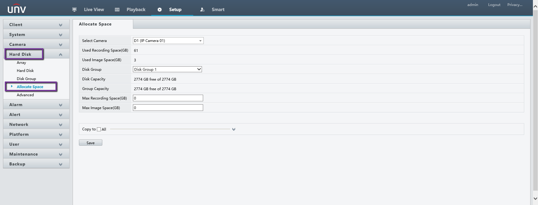
- Select Camera: Select which camera to configure.
- Disk Group: Specifies which disk group to configure the camera for.
- Max Recording Space: Determines the allocated storage size in GB for video recordings.
- Max Image Space: Determines the allocated storage size in GB for image snapshots.
- Copy: Allows copying of configuration to selected cameras.
Advanced
This tab will determine what the Network Video Recorder will do once the Hard Disk Drives are full and new footage needs to be saved. Setting this to Overwrite should allow the NVR to delete older footage to make space for new ones to be saved while setting this to Stop will prevent any new recordings to be saved.
Navigation: Setup > Hard Disk > Advanced
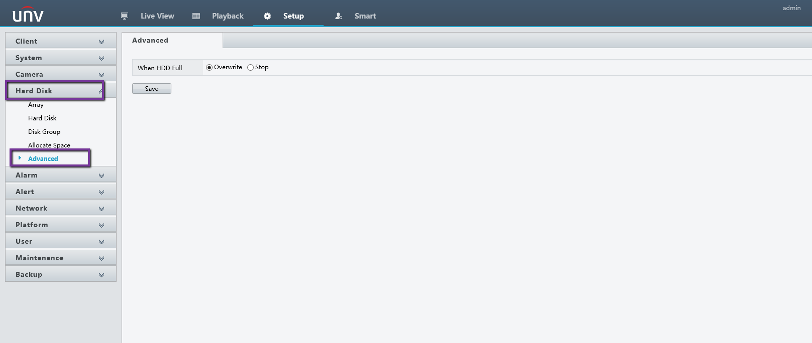
- HDD Full: Determines whether to overwrite old recordings or stop once the HDD is full.
How To Adjust Resolution, Frame Rate, Bit Rate, and Video Compression
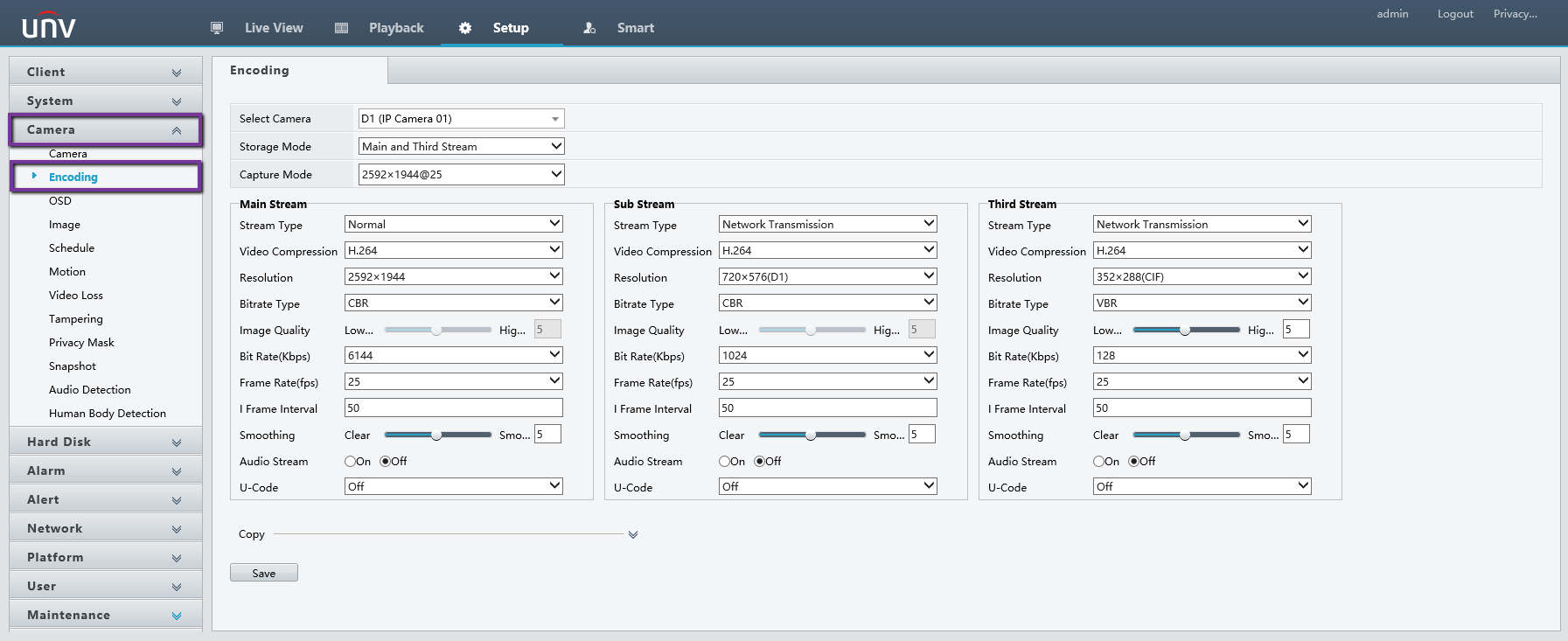
Adjusting the resolution, frame rate, bit rate, and compression of recorded footage can be done by navigating to the Encoding Tab.
Navigation: Setup > Camera > Encoding
-
- Navigate to the Encoding tab.
- Select which Camera to configure.
- Storage Mode: Select which stream to use for storing footage. By default, the mainstream is used for storage.
- Capture Mode: The options here are the presets you can use if preferred.
- Main/Sub/Third Stream: These sections allow greater configuration of each stream.
- Stream Type: Select your preferred stream type.
- Normal: main stream that is intended for scheduled recording.
- Event: main stream that is intended for recording triggered by events such as alarm inputs or motion detection alarms.
- Video Compression: Select your preferred video compression standard. The listed options depend on the standards supported by the camera:
- H.264
- H.264+
- H.265
- H.265+
- Resolution: Select your preferred resolution for the selected stream.
- Bit Rate Type: Select your preferred bit rate type.
- CBR: Constant Bit Rate is used to maintain a specific bit rate by varying the quality of video streams. It is preferred when limited bandwidth is available. The disadvantage is that video quality will vary and may decrease significantly with increased motion in the scene.
- VBR: When using Variable Bit Rate, video quality is kept as constant as possible, at the cost of a varying bit rate, and regardless of whether or not there is motion in the image. It is ideal when high quality is a requirement, especially when there is motion in the picture.
- Image Quality: This parameter is effective only when Bitrate Type is
set to VBR. 9 levels are provided. - Bit Rate (Kbps): Select your preferred number of bits transferred per second. Select a value or select Custom and then set a value as needed.
- Range: Select the bit rate range. Currently the range is fixed.
- Frame Rate (fps): Select the number of frames per second.
- I Frame Interval: Number of frames between two adjacent I frames.
- I Frame Range: Range of I frames. Currently the range is fixed.
- Smoothing: Use the slider to control the sudden increase of bit
rate. - Audio Stream: Enable or disable audio stream.
- Smart Encoding: The advanced mode achieves higher compression ratios.
- Stream Type: Select your preferred stream type.
How to Enable 2-Way Audio Via Web Interface
In this guide we will show how to enable two-way audio on a UNV camera, NVRs or NVRs via a computer/laptop. By doing that, you should be able to hear and speak back to the camera.
Please Note
To utilize the two-way audio feature, the camera must be equipped with a microphone and a speaker, they can be built-in, or installed separately if the camera allows it.
Enable two-way audio on Uniview cameras (or DVR/NVR)
Start by accessing the Uniview device via a web browser (use Internet Explorer and the computer has to be Windows). Type the IP address of the camera (or DVR/NVR) and the URL bar.
Install all requested web plugins that are prompted by Internet Explorer. Once installed, you may need to refresh, or restart the web browser.
You may install the plugin by selecting “Run”. In some instances, you may need to close the web browser to complete the installation. After installation completes, please re-open Internet Explorer. An example is shown on the screenshot below and the Uniview plug-in is called “UwareWebPlayer”.
Enable 2-Way Audio on UNV
After logging in, the Live View page will be where you will be able to use audio(2-way talk) features. If a camera supports 2-way audio, you will see that option (noted with the red circle).
Enable 2-Way Audio on UNV
Another option is using the RCA input and output directly on the back of the recorder to produce 2-way talk audio. This will be on the bottom of the Live View page. Sometimes the options are greyed out and that indicates that the audio is not supported by the camera.
Enable 2-Way Audio on UNV
Basically, if your camera supports audio, all you need to do is locate the audio buttons on the Uniview’s web interface and have them enabled. Make sure to unmute the PC’s audio as well, otherwise you won’t be able to hear anything.
Two-way audio enables the user to hear the live audio from the camera and, if necessary, to talk back. So the camera needs to have a microphone built-in and a speaker. If it has just a mic, then you can hear but you can’t talk back.
If you’re not sure if your camera is equipped with audio capabilities, just check the spec sheet or ask the Nelly’s for more information.
If the audio is not clear enough, or too noisy, it’s recommended not to install the camera close to noisy devices such as fans, AC units, or other appliances. Additionally you may need to update the camera’s firmware to the latest version.
Configuring Dual NIC NVRs
There are a lot of advantages to utilizing two network cards on a recorder.
The main advantage to using both NIC ports on a recorder is that cameras on the job can be on their own network away from the customer’s existing network, while still keeping the recorder on the main network to gain internet access for remote viewing.
Other reasons to use both NIC cards include load balancing to reduce camera video lag, and Net-Fault Tolerance which means the recorder will only take one IP address from the main network, and set up so if one port fails the other will take over.
Please Note
One thing to remember before setting up both NIC ports is that they CANNOT be on the same gateway/subnet. This will cause both ports not to work and the recorder will not give any warning when setting them on the same gateway/subnet.
Also remember that a monitor plugged directly into the recorder is needed to start the dual NIC setup
Multi Address
Multi-Address will allow for both NIC cards to be set on different Gateways from each other. This will allow for the recorder to be on the customer’s main network but then for the cameras to be on their own separate network without the need for a router.
- Plug NIC labeled 2 into the gigabit uplink on the cameras PoE switch, a standard PoE LAN port will work as well if an uplink port is not available.
- Plug NIC labeled 1 into the customers network, the recorder can be plugged into a switch, router, or modem directly.
- Next, on the monitor that is hooked directly into the recorder, right click and log into the main menu
- Navigate to System and then to Network settings.
- Once in the Network menu set the IP address for NIC1 to match the customer’s gateway. If the gateway is unknown set NIC1 on DHCP. DHCP will automatically pick a free IP address and set the correct gateway. (Note: Remember that if the customer has a 192.168.1.1 network this is the same default as NIC2 and will cause the ports not to work. If this is the case make sure to change the Selected NIC to NIC2 and then manually set the IPv4 Default Gateway to a different subnet and give it a matching subnet IP address)
- Next change the Selected NIC to NIC2 and then manually set the IPv4 Default Gateway to a different subnet than NIC1 and give it a matching IP address on the same subnet. For example if NIC1 is set to IP address: 192.168.1.30 and Gateway: 192.168.1.1, NIC2 will have to have a different gateway such as IP address: 192.168.20.100 and Gateway: 192.168.20.1. This puts NIC2 on the .20. subnet.
- After both NIC cards are set up to have different gateways, the cameras will then need to be addressed to match the gateway that NIC2 is set to. Continuing with the example above, the recorders IP address is: 192.168.20.100 and Gateway is: 192.168.20.1. This means that each camera will need to be set to the same gateway and each camera will need to be given a different IP address on that gateway. See below for example of the cameras IP address.
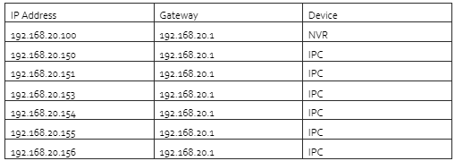
- Last set the Default Route in the recorder’s network settings to NIC2. This will set the recorder so when it reboots it looks to connect to the cameras on the second NIC port and NIC1 will stay active in the background.
At this point the cameras can now be searched for in the camera menu and added to the recorder.
Load Balance
Load Balancing is good for jobs that have a lot of cameras (64 or more) this will allow for both NIC ports to share the load of data and keep the cameras video images from lagging or skipping. The reason this is needed sometimes is because bit rates on cameras can quickly exceed what a 1 Gbps NIC port can handle.
- Plug both NIC1 and NIC2 ports into the customer’s main network, the recorder can be plugged
into a switch, router, or modem directly. - After both ports are connected to the network log into the recorder’s main menu and navigate to System > Network.
- Set the Working Mode to Load Balance.
- Select NIC should be set to Binding1
- Next set the IPv4 Address and IPv4 Default Gateway to match the customer’s network. If the default gateway is unknown, set the recorder on DHCP and save. After DHCP grabs an IP address, disable DHCP to keep the IP address static.
Net-Fault Tolerance
Net-Fault Tolerance allows for the recorder’s NIC cards to be set in a redundant state that allows one to take over for the other if the first one fails to operate correctly. This is good in situations where the recorder must absolutely always be on the network. This could mean that the job site is monitored off site at all times or has cameras from a remote location.
- Plug both NIC1 and NIC2 ports into the customer’s main network, the recorder can be plugged
into a switch, router, or modem directly. - After both ports are connected to the network log into the recorder’s main menu and navigate to System > Network.
- Set the Working Mode to Net-Fault Tolerance.
- Select NIC should be set to Binding1
- Next set the IPv4 Address and IPv4 Default Gateway to match the customer’s network. If the default gateway is unknown, set the recorder on DHCP and save. After DHCP grabs an IP address, disable DHCP to keep the IP address static.
How To Setup Multicast Addressing
Multicast can be used to pull up live view when the number of connecting Web clients exceeds the limit the NVR can accommodate.
1. Click System -> Network -> Multicast.
2. 2. Select the check box to enable multicast, and then enter the multicast IP and port number.

3. Click Apply to save the settings.
4. Log in to the Web client and set Live View Protocol to Multicast under Setup -> Client.
Note
Set the multicast IP correctly. Multicast address is class D address with the range 224.0.0.0 through 239.255.255.255
Reference
– 224.0.1.0–238.255.255.255 can be used on the Internet.
· 224.0.0.0-244.0.0.255: only for use on LAN.
· 224.0.0.1: all-hosts group address, which refers to all the multicast-capable hosts and routers on a physical network.
· 224.0.0.2: for all routers on this subnet.
· 224.0.0.5: for all OSPF routers.
· 224.0.0.13: for all PIMv2 routers.
· 239.0.0.0–239.255.255.255 are for private use like 192.168.x.x.
How To Manually Upgrade a UNV NVR Via Web Interface
If your NVR is accessible on the local area network using the web interface, you may update the
firmware using a file that has been downloaded and stored locally.
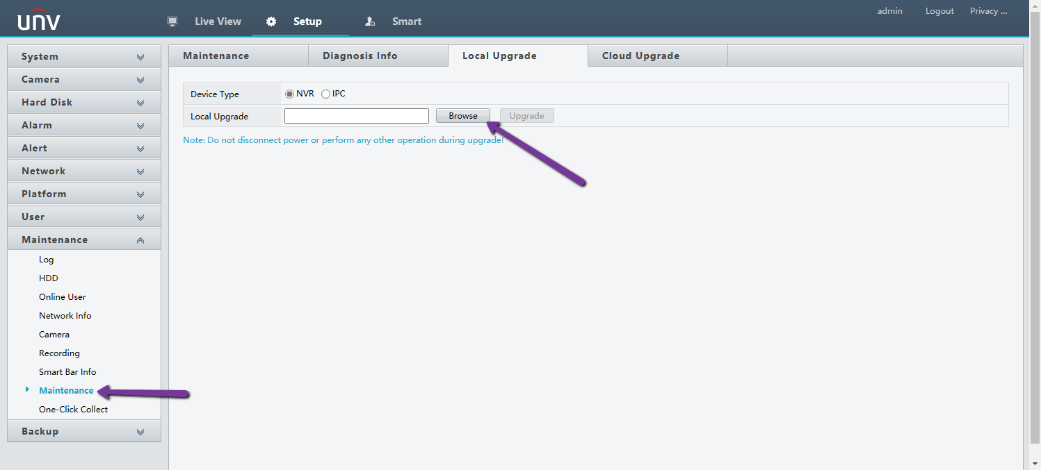
Within the Setup section of the web interface, go to the Maintenance section and select the Local Upgrade entry. On the screen that comes up, click on the Browse button next to the Upgrade text entry field and browse to the location on the local PC where the firmware file is stored and click on it. Once the file is properly entered, press the Upgrade button and the unit will perform the upgrade procedure including a reboot which will terminate your connection.
Please Note
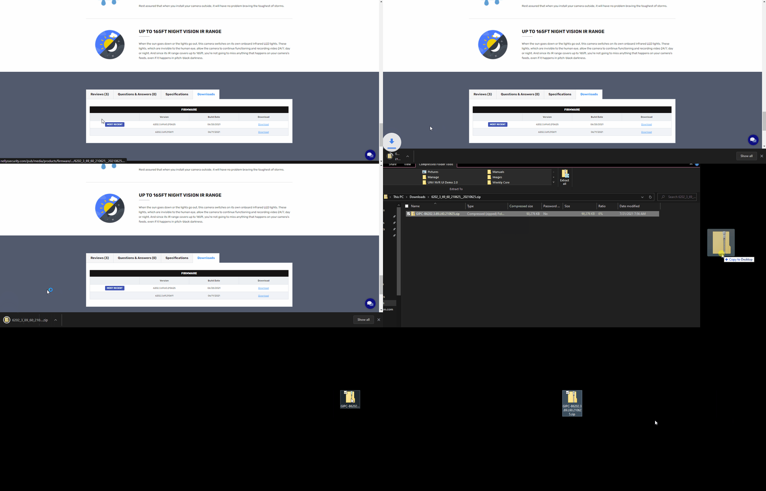
If you download a firmware off the Nelly’s website, you must export the Zip Folder out of the initial Zip Folder that is downloaded.
How to Export Footage Via Web Interface
Uniview allows the user to have the capability of exporting footage via its web interface. This is quite handy in case the attached monitor UI is not accessible.
This guide is for after the device has a storage drive installed and formatted. As well as recording schedule set.
Step 1 – Navigating To Playback
First, you will input the device’s IP address into the address bar in a web browser. In this guide, we are using Edge running in IE mode.
Once you are logged in, across the top of the page, select the Playback Tab
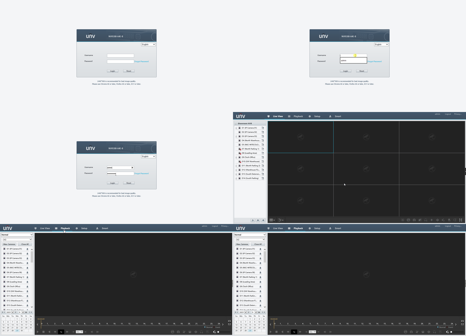
Step 2 – Exporting Process
Once in the Playback section, you will see a list of cameras on a left column with Download icons next to them.
Click on the Download icon and a new popup window will appear.
From here, you can select all of the cameras that you want to export footage from.
There will be a Start Time & End Time selection for the clips.
Once you have the parameters selected, hit Search.
Afterwards, a list of clips will appear below, select the clips you would like. Also, if you’d like the clips to be merged together, select the Merge and Download checkbox.
When all the selections are selected, hit the Download Button.
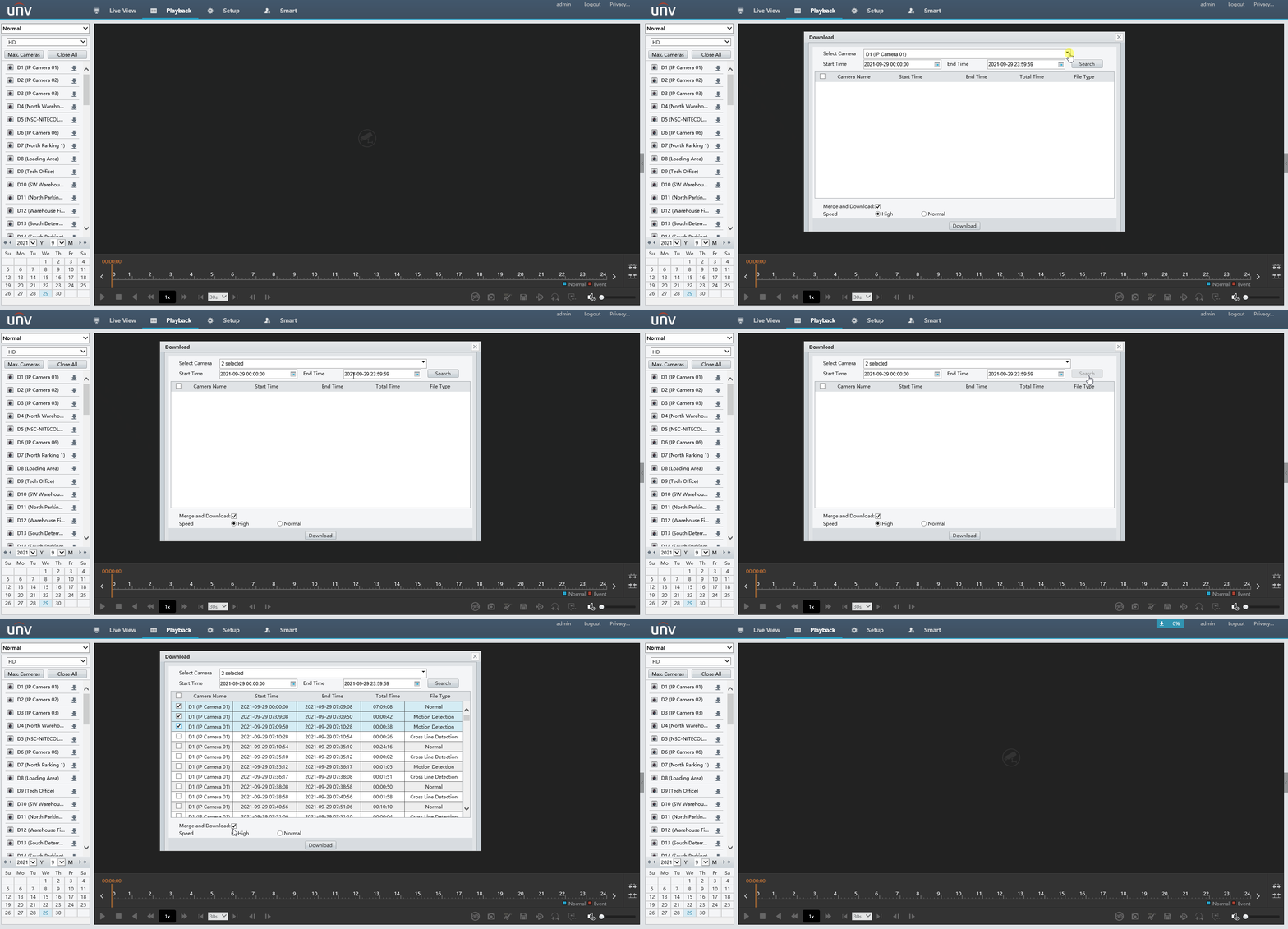
As the files are downloading, you will get a status bar at the top right of the screen and once the files are done, a hyperlink will appear for you to click to pull up the files. 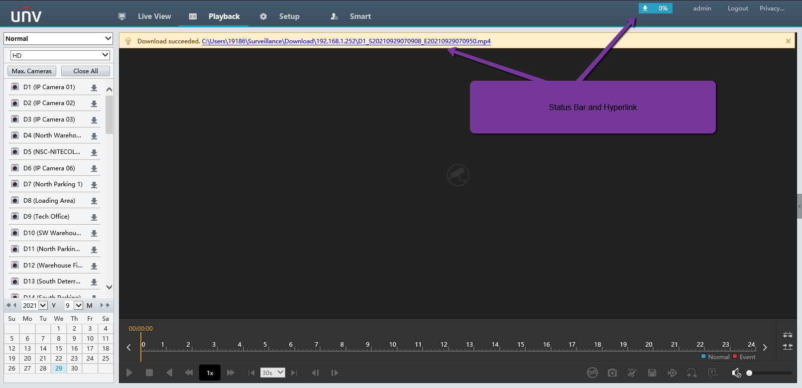
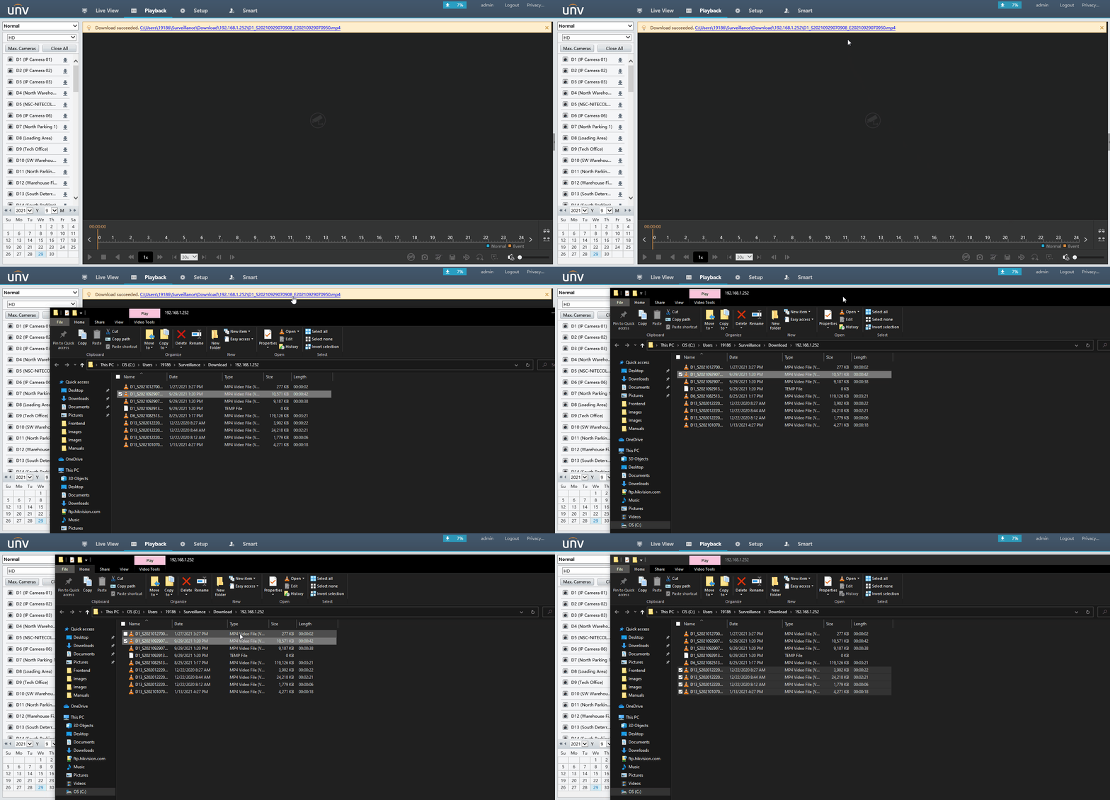
To view the exported footage, you can use either VLC Player or Uniview’s EZPlayer
How to Use Extended Transmission Mode
Long Distance POE/Data Transmission
One problem that a lot of installers run into with IP jobs is Cat5E cable length limitations. With the cable
limitations this requires that some job sites have extra equipment installed such as another switch or
extender. Installing extra devices not only creates more fail points on the job site but it can drastically
increase the price of the job. Uniview offers an incredible solution to this problem! Using Uniview built
in PoE recorders cameras can now be ran up to 300M (900 FT) over Cat5E plenum.
Enabling Long Distance Mode
Enabling long distance mode is very simple, log into the main menu of the recorder and navigate to the
Camera menu. In the camera menu each channel that has a PoE port built in to the recorder will already
have a channel spot reserved for them with an IP address. Double click on one of the reserved channels
to display the channels Modify menu. The last option in the Modify menu will be a check box to enable
Extended Transmission mode. Check this box on and then click the Modify button at the bottom.
Using A Uniview Switch
There is a small extended mode switch in the bottom corner of each uniview switch, this switch comes
off by default. Enabling this switch can give the same performance as a built in PoE switch when it
comes to long distance transmission. Installers will need to use Cat5e Plenum cable though. Each
Uniview PoE switch also comes with at least one gigabit uplink port and one fiber port.
Enabling The Extended Mode Switch
- Power on the switch without plugging anything into it.
- Turn the extended mode switch to the “on” position.
- Unplug the switch / Turn off the switch for 30 seconds.
- Power the switch back on.
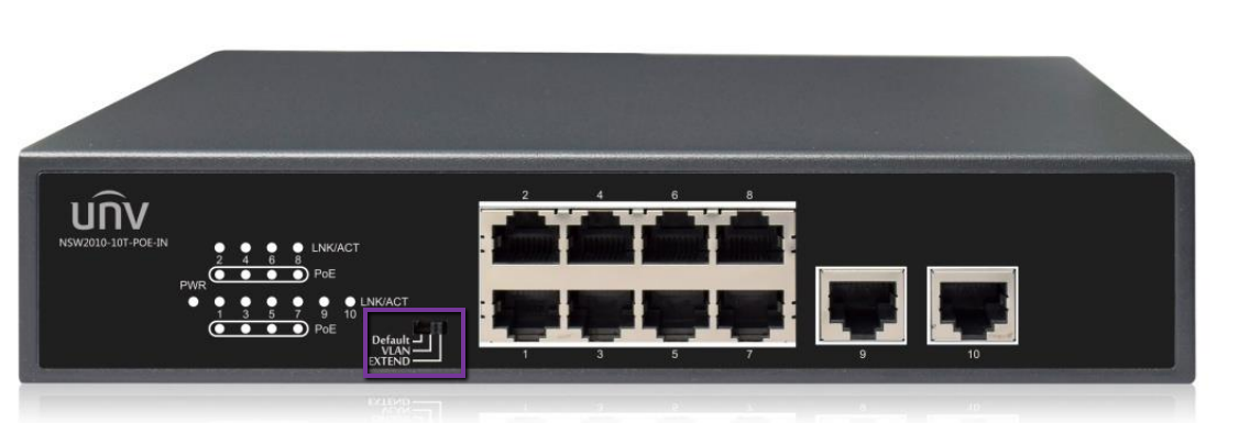
The switch will be in extended mode when the switch comes back on. Once in Extended mode the PoE
ports will all act individually without the ability to see the other PoE ports. Make sure that the NVR is
plugged into the gigabit uplink port otherwise it will not be able to see the cameras. If daisy chaining
switches together the gigabit or fiber ports will need to be used to link each switch and then connected
to the main network using the first switches second uplink (8 port switches cannot daisy chain without
an extra dummy non PoE switch to link everything.)
If daisy chaining switches together each switch will need to be link together by each switches uplink
ports. The NVR would then be plugged into the first switch in the chains second uplink port. And the
internet would need to be plugged into the last switch in the chains second uplink port.
Camera Limitations
Fixed lens cameras: 900 Feet
Motorized Lens/Base Cameras: 600 Feet
PTZ: 330 Feet
Adding Blank UNV Camera To UNV Retail NVR via Plug n Play
In scenarios where a Blank UNV camera is paired with a UNV Retail NVR, these will be plug n play. However, you may not get the full functionality of the Blank UNV Camera right away.
In this guide, we will show you the steps needed to allow the full functionality of the Blank UNV Camera.
Connecting The Camera
Since the Blank UNV cameras are plug n play with UNV Retail NVRs, the camera will come online if it is connected directly to the integrated POE switch of the NVR.
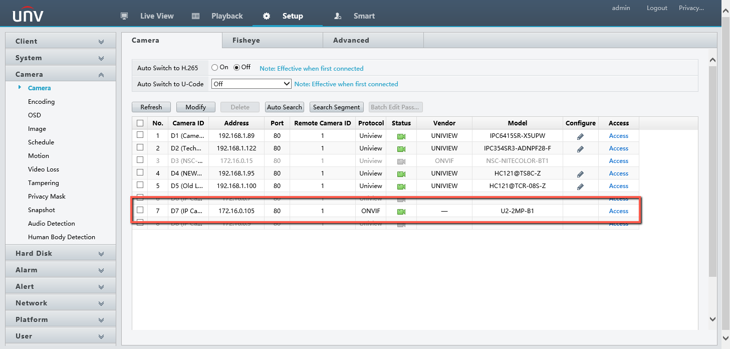
Camera Configuration via NVR
One thing you may notice however, the camera will show added with the ONVIF protocol. This can be very limiting as ONVIF only guarantees a live view and 24/7 recording.
If you go into the Smart Event section of the NVR while the camera is added via ONVIF, you will notice that none are available:
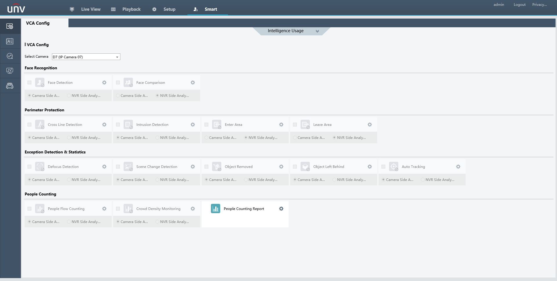
To accommodate for this, Go to Setup -> Camera -> Cameras. Checkmark the Camera, select Modify, change the Add Mode to IP Address, then change the Protocol to Uniview. Save.
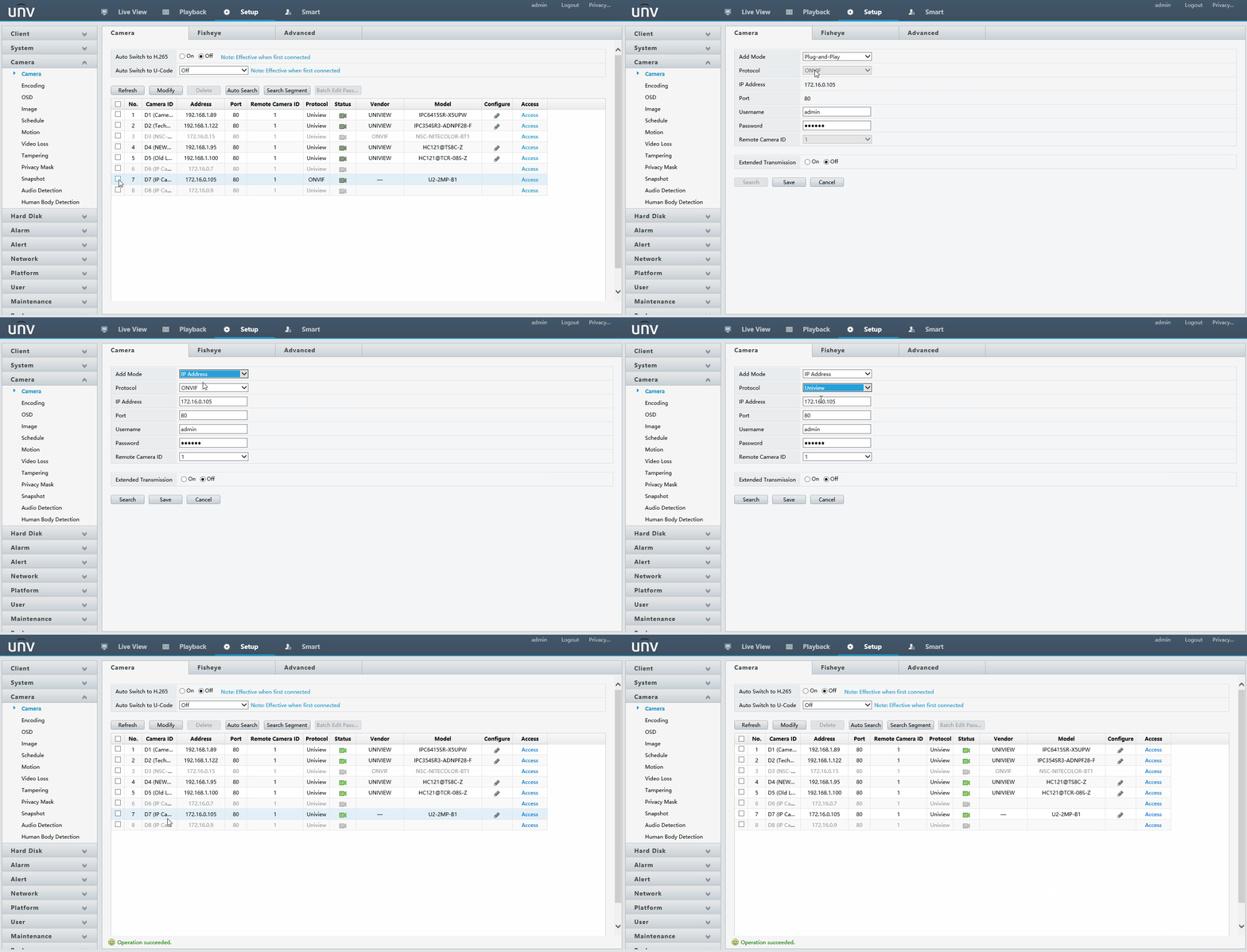
Now that the camera is talking via the Uniview protocol, the Smart Events are now available!
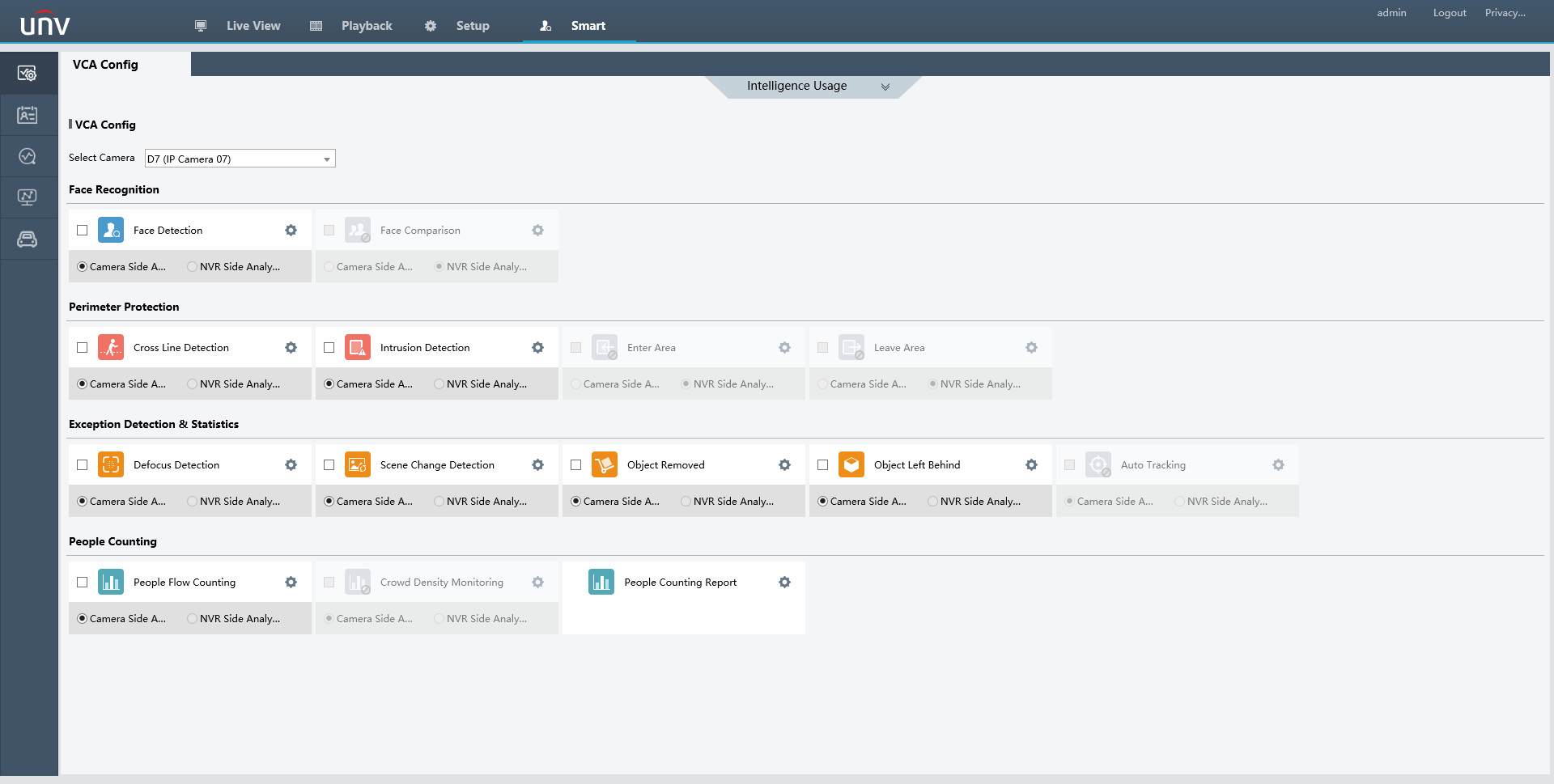
Please Note
Not all UNV cameras support Smart Events, be sure to verify what events the camera supports beforehand! If you are unsure what events a camera may support, feel free to contact our Support or check the camera’s spec sheet.
Also Note
This guide will work along with UNV Retail Cameras and UNV Blank NVRs. Just the protocol will be changed to Private instead of Uniview on the Blank NVR.
How To Export Footage Via EZstation
In this guide, EZStation is already installed on the user’s computer, and the recording device has already been added to the software’s device list.
Step 1 – Accessing Playback & Exporting
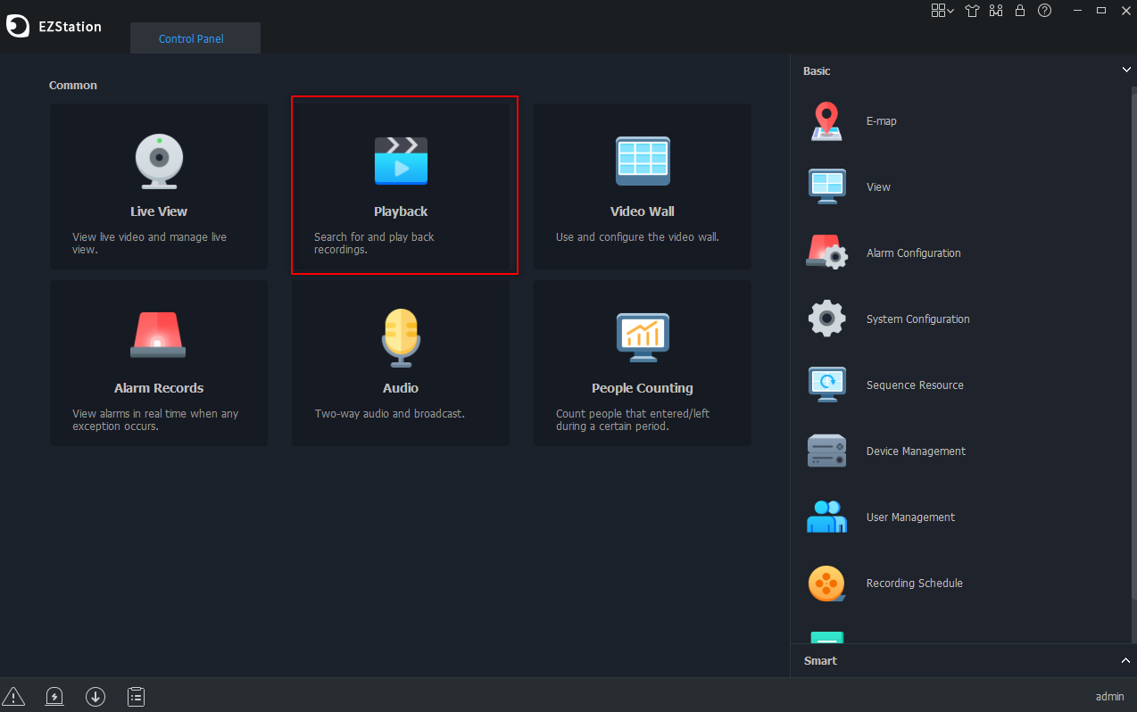
From the Control Panel, select the Playback Tab to access the playback section of EZStation.
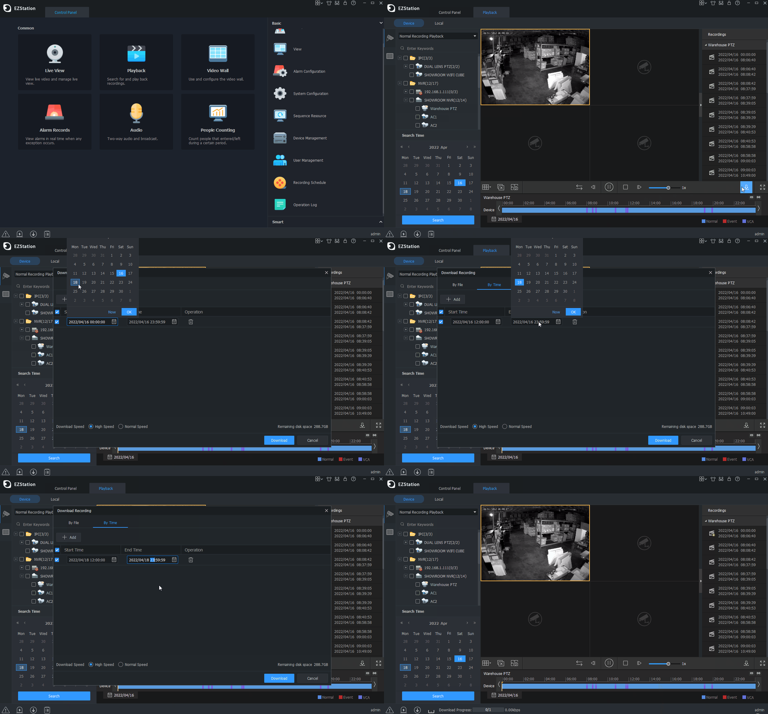
From the Playback Section, On the left-hand side, click on the “+” next to the NVR/DVR, the camera will drop down. Then select one camera on the left-hand side to playback and save footage from. Once the camera is selected, the calendar should populate with Blue or Red dots to indicate what type of footage was recorded on that day.
- Blue = Normal
- Red = Event
- Purple = VCA
After the day has been selected, Click the Search icon under the Calendar.
Next, select the download icon ” ![]() “. Then select the “By Time” tab and input the timeframe that you want to export footage from. When this has been done, select the Download icon.
“. Then select the “By Time” tab and input the timeframe that you want to export footage from. When this has been done, select the Download icon.
Step 2 – Finding Saved File
To find where the saved exported footage went, you can select the Download Progress at the bottom of EZStation.
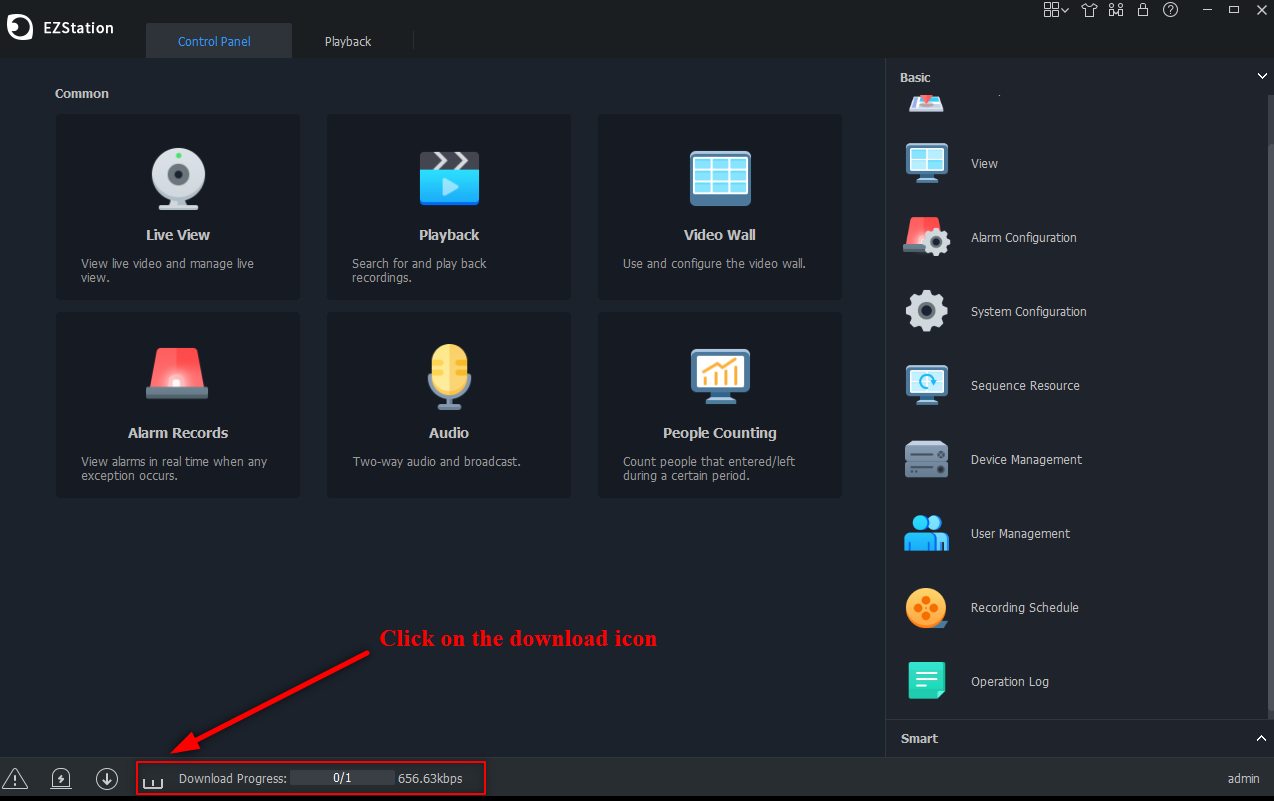
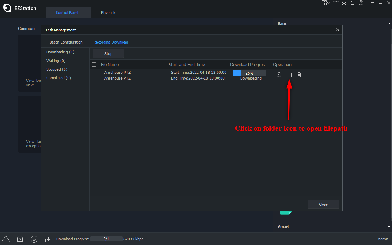
After the Download Icon has been clicked, a popup window will appear. From that popup window, there is a folder icon that can be selected to open the file path on your computer.
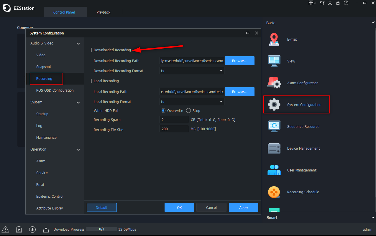
To change the File Path, from the Control Panel in EZStation, select the System Configuration icon, then Recording Tab.
How To Backup Recording Via HDMI Interface
Backup, also known as recording backup, is the process of querying video stored on a hard disk of
the NVR and then saving to a USB storage device as a file.
Recording Backup
Recording backup has the following conditions:
- Back up using a USB storage device: format the partition in FAT32 or NTFS format; connect
the storage device correctly to the NVR. - Permission is required.
- The recording to back up is stored on a hard disk of the NVR
Note: The default file format is .mp4 when you back up recordings to a USB storage device.
Normal Backup
- Click Backup > Recording. All cameras are selected by default.
- Set search conditions and then click Search. Search results are displayed.
- Note: You can lock/unlock and play recording files in this window.
- Select the desired recording(s) and then click Backup.
- Select a partition
- Back up to USB storage device
Set the destination in the USB storage device and then click Backup. The recording(s) will be
saved to the specified directory.
Note: You may want to create a new folder for the recording(s) by clicking New Folder.
Note: If the connected storage device has a capacity that is greater than 2T, clicking Format will
format the device to NTFS file system; if the capacity is 2T or less, the device will be formatted to
FAT32 or NTFS. Only certain devices can format a storage device that has a greater capacity than
2T.
Note: A progress bar (e.g., Exporting X/Y) is displayed to indicate the progress, where X indicates
the current number being backed up, and Y indicates the total number of recordings. To cancel
the operation, click Cancel.
Note: A backup file is named in this format: camera name-recording start time. File extension. For
example, Ch11-20220630183546.mp4.
Video Clip Backup
A recording can be clipped and saved to a USB storage device
- Open the playback window
- After playback starts, click
 and
and  on the playback toolbar to clip videos.
 - Click
 and then click the Video Clip tab to view video clips.
 - Select the desired video clip(s) and then click Backup.
- Select a destination in the USB storage device and then click Backup. The selected video clips
are saved to the specified directory
Image Backup
The default format of image backup is JPG
- Click Backup > Image.
- Set search conditions and then click Search. Search results are displayed
- Note: The image resolution depends on the resolution from the output interface and the number of windows displayed when the snapshot is taken.
- Select the desired file(s) and then click Backup
- Select a destination in the USB storage device and then click Backup. The selected files are
saved to the specified directory.



Add Comment