|
Number |
Item |
Description |
|
1 |
DC POWER IN |
DC power input port. Requires a 12V DC Power Adapter. |
|
2 |
AUDIO OUT |
RCA connectors for audio output. Allows for connection with audio output devices. |
|
3 |
USB |
Connector for USB device. Allows for connection with external hard drives, flash drives, USB mouse, or USB keyboard. |
|
4 |
HDMI |
High definition audio and video signal output port. It transmits uncompressed high definition video and multiple-channel data to the HDMI port of the display device. |
|
5 |
VGA |
VGA video output port. Output analog video signal. Can connect to the monitor to view ananlog video output. |
|
6 |
eSATA |
eSATA port. Allows for connection of an eSATA HDD for recording or backup purposes. |
|
7 |
LAN |
Ethernet port. Allows for connection to a Local Area Network (LAN). |
|
8 |
POE ports |
Connector for POE IP camera. |
Right Button:
Scroll-wheel:
When a mouse is used to perform tasks on the NVR, clicking on a text input field will bring up the Soft Keyboard.

![]()
![]()
![]()
![]()
![]()
The buttons on the soft keyboard represent:
Lowercase: Designates lowercase input is being used.
Uppercase: Designates uppercase input is being used.
Backspace: Delete the character behind the cursor.
Space
Space: Input spaces between letters.
Enter: Confirm selection.
ESC: Exit out of Soft Keyboard.
3 Device Installation
When you receive the NVR system in the packaging, unpack it, and check all sides of the NVR to see if there is any physical damage. The protective materials used for the packaging of the NVR can protect most accidental damage during transportation, but to ensure that your equipment is operating as expected, it is recommended to inspect the product before proceeding further.
On the NVR unit, check specifically that the label on the bottom of the NVR is not damaged. The serial number of the unit is usually needed to provide support.
Please check that all required items for your NVR are present and accounted for. To check what is included with your purchase, go to http://qcam.com/ and find the product you purchased, then scroll down and click the “What’s Included” tab. If any item is missing, please contact us as soon as possible so we can send you the missing component.
6. Connect the HDD cable and power cable.

 Note:
Note:
7. Put the cover on in accordance with the clip and then place the upper cover
8. Secure the screws in the rear panel and the side panel.
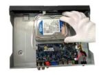
An HDD is included with the NVR by default.
To connect the HDD, connect the HDD data cable and the power cable before attaching the HDD in the device.
• To remove the front cover, push the clip first, and then slide the cover off.
|
1. Loosen the screws of the upper cover and side panel. |
2. Attach four screws in the HDD (Turn three times). |
3. Place the HDD in accordance with the four holes on the bottom. |
Please check to make sure the input voltage is correct and the power button is in the off position when connecting the power supply.
We recommend you use an Uninterruptible Power Supply (UPS) to guarantee steady operation of the NVR, as well as to elongate the life span of the NVR and other peripheral equipment such as attached cameras and other accessories.
The audio output signal parameter is usually over 200mv 1KΩ (BNC or RCA). It can directly connect to a low impedance earphone, active speaker, or amplifier-drive audio output device. If the speaker and the microphone cannot be separated spatially, it may create a feedback loop. In this case you can adopt the following measures:
3.4 Device Assembly Guide
Before setting up the NVR, you will probably need the following items. The items are not included:
Note: It is recommended to connect all components of the system as shown below BEFORE mounting any of the cameras. This is to ensure all components are working. If any components are not functioning, please contact Qcam Support.
To set up the NVR hardware, there are 6 major steps:
2. Connect a USB mouse to the front of the NVR.
3
Connect an Ethernet cable to your router, and then connect the other end of the cable to the NVR.
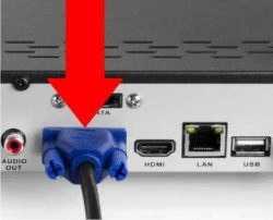
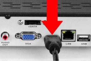
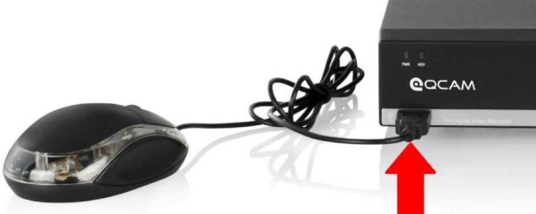
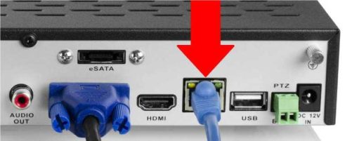
4. Connect the camera cable to an Ethernet cable.
5. Connect the Ethernet cable to a port on the back of the NVR.
6. Connect the NVR power cable into the back of the NVR, and then plug in the NVR power adapter into an electrical socket.
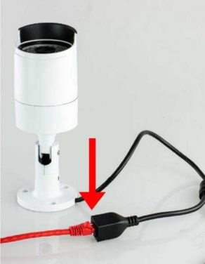
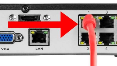
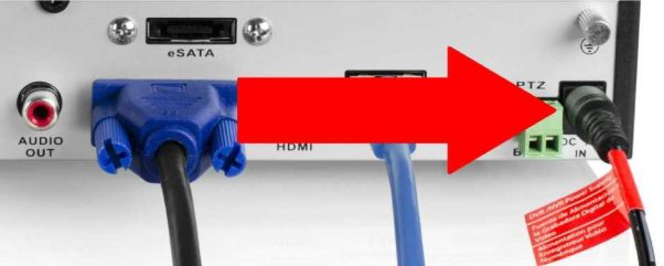
Proper startup and shutdown is crucial in ensuring the longevity of the NVR. To startup the NVR, please connect the NVR to power as specified in section 3.4. It is highly recommended to connect the NVR to an Uninterruptable Power Supply (UPS) in order to ensure continued recording even in the case of a power outage. The power indicator LED on the front of the device should turn on indicating the device is receiving power.
To shut down the NVR, follow the instructions below:
After turning the system on, the default video display shows multiple windows. To bring up the login screen, left click the mouse or hit enter on the keyboard. The login screen should look like this:
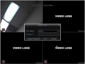
To login to the system for the first time, use the administrator account information below. Upon login for the first time, you have to setup the initial password for your device.
Username: admin
By default, your NVR comes with one user account, the Administrator account. The Administrator user name is admin. However, there is no default password for admin account. You have to setup a password when you login in the device at the first time for security reasons. The Administrator has the authority to add, delete, and configure parameters for many of the system functions.
Note: If three failed logins are attempted within a 30 minute time period, the system will set off an alarm. After five login failures, the account will be locked.
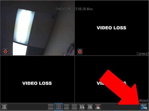
To initiate the setup process, click the Setup Wizard button from the main screen:





Add Comment