•Start Time: This field allows the user to select the start date and time to backup.
• End Time: This field allows the user to select the end date and time to backup until.

.
Click the Backup button to open the backup file list
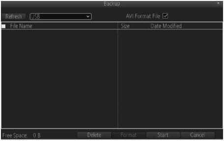
Use the checkboxes to select the files to backup, then click next to bring up the backup device screen:
.
Choose a backup device, then click Start to begin the backup.
Below is an explanation of the fields on this screen:
•Channel Status: This set of checkboxes allows the user to choose the camera/channel to view events for. The
channel number is the same as the number written on the rear panel next to the Ethernet port used to connect the camera.
•Video Type: This dropdown box allows the user to select which type of event to search for.
•Start Time: This field allows the user to select the start date and time to view events for.
•End Time: This field allows the user to select the end date and time to view events for.
Below is an explanation of the fields on this screen:
•Major Type: This dropdown box allows the user to select a type of log entry to select.
•Minor Type: This dropdown box allows the user to select a subtype of log entry to select.
•Start Time: This field allows the user to select the start date and time to view log entries for.
•End Time: This field allows the user to select the end date and time to view log entries for.
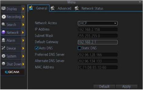
The network menu is where the user can configure different network settings to enable access to the NVR in a wide variety of ways, as well as to view the network status of different connected devices.
.
Below is an explanation of the fields on this screen:
•Network Access: This dropdown box allows the user to select which type of network access method to
configure. The options are Static, DHCP, and PPPoE. Selecting PPPoE changes the screen to include fields for entering PPPoE login information.
•IP Address: This field allows the user to manually enter an IP address. This field is grayed out when DHCP is
selected.
•Subnet Mask: This field allows the user to manually enter the subnet mask. This field is grayed out when DHCP
is selected.
•Default Gateway: This field allows the user to manually enter the default gateway.
•Auto DNS/Static DNS: These checkboxes show the user how the DNS is configured. When Network Access is set to Static, then the Static DNS box is checked, and when Network Access is set to DHCP, the Auto DNS box is checked.
•Preferred DNS Server: This field allows the user to manually enter in a preferred DNS server. This field is only active when Network Access is set to Static.
•Alternate DNS Server: This field allows the user to manually enter in a preferred DNS server. This field is only active when Network Access is set to Static.
•MAC Address: This field shows the user the NVR’s MAC Address.
.
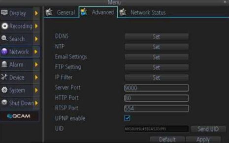
Below is an explanation of the fields on this screen:
•DDNS: This button allows the user to modify DDNS settings for the NVR. This will send the user to the DDNS
menu where DDNS settings can be modified. This is the most common method for setting up remote access to the NVR.
•NTP: This button allows the user to modify NTP settings for the NVR. This will send the user to the NTP menu
where NTP settings can be modified. This allows the NVR to sync time and date settings with the global NTP standard.
•Email Settings: This button allows the user to modify email settings for the NVR. This will send the user to the Email Settings menu where email settings can be modified. This is necessary to configure for use in email alerts.
•FTP Settings: This button allows the user to modify FTP settings for the NVR. This will send the user to the FTP menu where FTP settings can be modified.
•IP Filter: This button allows the user to modify IP Filter settings for the NVR. This will send the user to the IP Filter menu where IP Filter settings can be modified.
•Server Port: This button allows the user to set the server port.
•HTTP Port: This button allows the user to set the HTTP port.
•RTSP Port: This button allows the user to set the RTSP port.
•UPNP Enable: This checkbox allows the user to enable the use of UPnP protocol on the device.
•UID: This field shows the user the NVR’s UID and allows the user to send it.
Below is an explanation of the fields on this screen:
•Net Status: This field shows the user what the status of the network is.
•IP Address: This field shows the user the IP address of the NVR.
•Subnet Mask: This field shows the user the subnet mask of the NVR.
•Default Gateway: This field shows the user the default gateway of the NVR.
•Preferred DNS Server: This field shows the user the NVR’s preferred DNS server address.
•Alternate DNS Server: This field shows the user the NVR’s alternate DNS server address.
4.6.6 Alarm
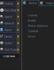
The alarm menu is where the user can set up motion detection, video loss, or exception alarms.
.
Below is an explanation of the fields on this screen:
•Channel: This dropdown box allows the user to choose the camera/channel to edit.
•Enable: This field allows the user to enable motion detection for the specified channel.
•Motion Detection: This button allows the user to set motion detection zones for the specified channel.
•Schedule: This button allows the user to set the motion detection schedule for the specified channel.
•Action: This button allows the user to set actions that occur when a motion detection alarm is triggered for
the specified channel.
Follow these steps to setup motion detection on the Qcam NVR:
1.Select the channel you want to configure.
2.Check the Enable checkbox to enable Motion Detection.
3.Click the Set button next to Motion Detection to configure the motion detection areas and sensitivity for that channel. Right click and select sensitivity to configure sensitivity settings. Right click and select save to exit the screen and to save motion detection area settings.
4.Click the Set button next to schedule to configure the schedule for motion detection. Click Apply when finished to save the settings.





Add Comment